In Step 2, you delete the old pile group and then specify a new group.
The pile group specified in Tutorial 4 was a 2 x 2 group. You can see this most easily by changing the orientation of the Drawing Board to plan view. To do this, right-click anywhere on the Drawing Board and select Plan. Alternatively, select the Drawing Board tab on Repute’s ribbon and then click on the Plan button.
You may also find it easier to see the piles if you increase the Drawing Board’s scale. To do this, right-click anywhere on the one of the rulers at the edge of the Drawing Board and select 1:200. Alternatively, there are buttons on the Drawing Board tab (on Repute’s ribbon) which allow you to manipulate the scale however you choose.
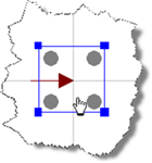
If you move the mouse over the drawing of the pile group in the Drawing Board, a balloon will appear showing its name (which is “Pile Group 1”). You can select this group by clicking on it, whereupon a blue selection rectangle will appear with square “handles” at each corner. “Pile Group 1” will automatically be highlighted in the Project Manager and its properties displayed in the Property Inspector.
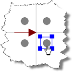
If you now move the mouse over one of the piles within the group and click on it, a balloon will appear showing the pile’s name (e.g. “Pile 4”). You can select this pile by holding the Ctrl key down and clicking on it, whereupon a blue selection rectangle will appear with square “handles” at each corner. “Pile 4” will automatically be highlighted in the Project Manager and its properties displayed in the Property Inspector.
To delete this pile from the project, right-click on it in the Project Manager and select the Delete command located under the Edit sub-menu. You will be asked whether you are sure you want to delete ‘Pile 4’ (Bored Pile) and reminded that this pile is being used by ‘Pile Group 1’ (Pile Group). Click Yes to confirm the command, whereupon Pile 4 will disappear from both the Project Manager and the Drawing Board.
Repeat the previous instruction for Piles 1-3 and, finally, for Pile Group 1.
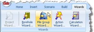
Next, open the Pile Group Wizard by selecting the Wizards tab on Repute’s ribbon and clicking on the Pile Group Wizard button.
When the Wizard appears, choose the Custom plan arrangement and change the number of pile rows to m = 5 by n = 3. The picture on the left-hand side of the Wizard will change to show you a (generic) rectangular pile arrangement.
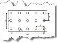
Change the Spacing between the piles to 3m, but leave the Cover at its default value (200mm).
Click Next to display the next page.
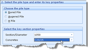
Choose ‘Bored pile’ as the pile type, change the Section/Diameter to 1050mm, and select C20/25 as the Concrete grade to be used. By default, this concrete has Young’s modulus of 30 GPa.
Click Next to display the next page.
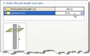
Change the Embedded length (L) to 20m but leave the Upstand (U) as 0m.
Click Next to display the next page.
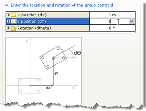
Change the X position (dX) of the pile group‘s centroid to 6m, its Y position (dY) to 3m but leave its Rotation (dθ) as 0̊. This will position most of the piles in the group close to their desired positions.
Click Next to display the next page.
Tick “Stage 1” to add the pile group to the scenario.
Click Next to display the last page.
If you wish to review any of the settings you have made, click Back to return to the relevant page. Otherwise, click Finish to generate the pile group.
The Pile Group Wizard then:
Creates Piles 1-15
Creates Pile Group 1
Creates Concrete 2
Links Piles 1-15 to Concrete 2
Adds Piles 1-15 to Pile Group 1
Adds Pile Group 1 to Stage 1
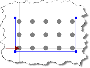
The Drawing Board will now look something like the image below (with the pile group selected):
A copy of this step can be found at [Projects]\Tutorial 6\Step 2.rpx.
Step 3 - move the piles to their final positions